Most articles that talk about enlarger alignment tell you how to do it, but don’t explain how it can be a never ending battle. For me and my two Omega D5s, the mechanisms that throw my enlarger out of alignment are drop-away baseboard tabletops and different negative carriers.
Baseboard Alignment Error
My enlarger is bolted to the wall and the table is mounted below it. To make larger prints or for more extreme cropping, I can remove the upper tabletop and project down to a lower table top. I can also remove the lower tabletop and project all the way to the floor.

Removable Tabletops (projection surfaces)
Both of my enlargers are configured similarly. The tabletops are 3/4″ plywood supported on three or four sides and they are not perfectly parallel, although they are close. For most routine printing, they don’t introduce enough error to worry about, but when I am being very critical and exposing at wide apertures to avoid diffraction issues, I will align the enlarger for the specific configuration in use.
Negative Carrier Alignment Error
Omega has two main types of negative carrier. First is the two-piece sandwich and second is the spring loaded Raid Shift carrier.
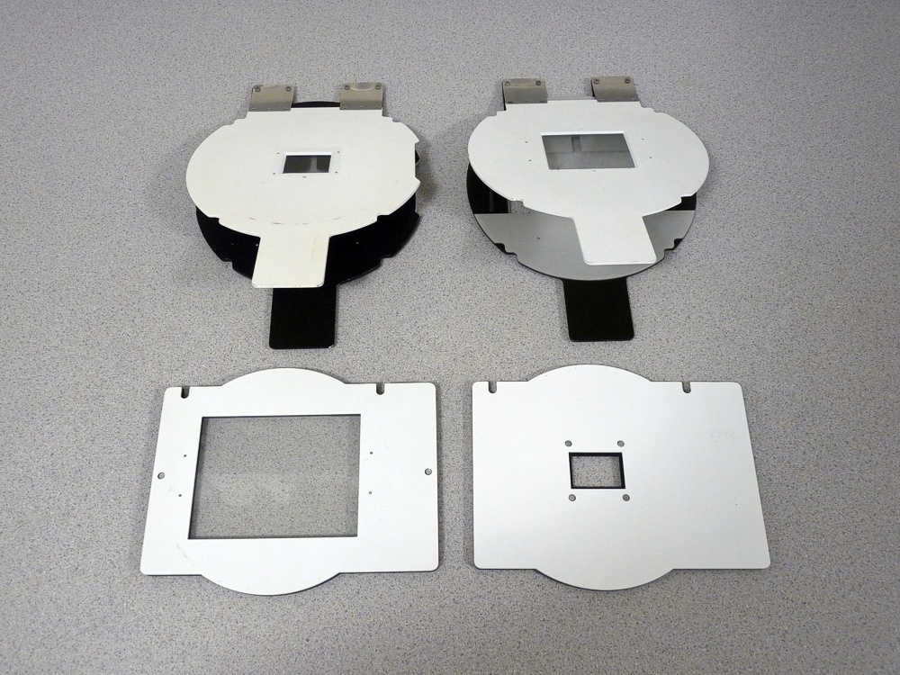
Rapid Shift (top row) and sandwich style (bottom row)
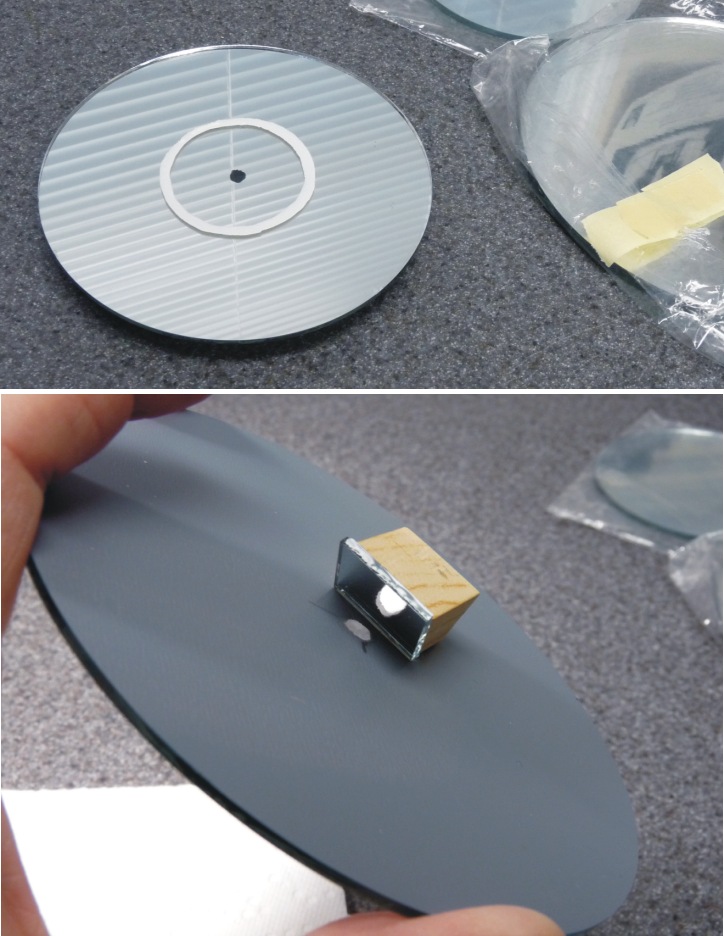
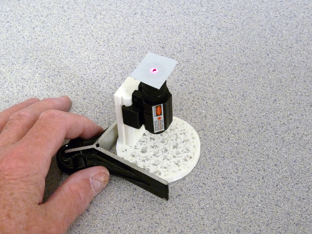
Each of these carriers can be further divided into glass and glassless. I use glass carriers exclusively. In theory, when the Omega lamp house is lowered onto these carriers, they are compressed perfectly flat eliminating any chance of injecting alignment error. The reality is different. I align my enlargers using a laser alignment tool. Once I have the enlarger aligned for one carrier, I would expect all my other carriers to behave the same. They do not. The rivets in these carriers warp the metal slightly. The spring tabs at the rear of the Rapid Shift carriers are also cable of preventing the two haves from lying perfectly flat.
Finally, the glass thickness may not be precisely correct for the film thickness, causing a slight bowing of the carrier when the lamphouse is lowered onto it. My carriers have a mix of original equipment clear and anti-Newton glass from Omega, Focal Point, and some that came installed in carriers purchased from ebay.
What I have found is that my laser alignment tool shows that aligning with one carrier, does not always mean all carriers will be in alignment. Furthermore, lowering the lamphouse onto the carrier may also also alter the alignment. Granted, the shift is not great, but it is enough to shake my confidence that I will get corner-to-corner sharpness in a large print at wide apertures. Large, for me, is 16″ x 20″ or 20″ x 24″.
While there is no easy fix to this dilemma, anyone who uses a view camera knows that lens adjustments (swings and tilts) can be used to match a plane of focus to a non-parallel film plane using the Scheimpflug Principle. Stated another way, the lens plane can be adjusted to accommodate any errors in alignment between the enlarger film plane and the easel. Besseler did exactly that when they offered a lens board called a Bes-Align. It has three adjustment screws to allow an enlarger lens position to be adjusted in a way that can be used to accommodate a misalignment between film and easel.

Bes-Align
The adjustable lens board can be used in conjunction with a Micromega or Peak grain focuser to tweak the lens plane as required to ensure the corners the image projected onto the easel are in focus. It provides a quick way to fine tune enlarger alignment to compensate for errors introduced by different negative holders or baseboard (table top) configurations.
I made a version of the Bes-Align to fit an Omega D5 years ago. I simply attached a lens mounting plate to an Omega lens board using three machine screws with an 3/16 inch layer of black foam between the plate and the lens board. The foam serves as a light seal and as a spring to act against the three adjustment screws.

My copy of the Besseler Bes-Align adjustable lens board to fit an Omega D5 enlarger.
My copy of the Be-Align was functional, but I wanted something deeper that would accommodate the rear extension of my El-Nikkor lenses, so I decided to add a spacer and make it more rigid with actual springs rather than relying on the resilience of the foam rubber spacer.

Improvements included springs and a 1/4″ spacer.
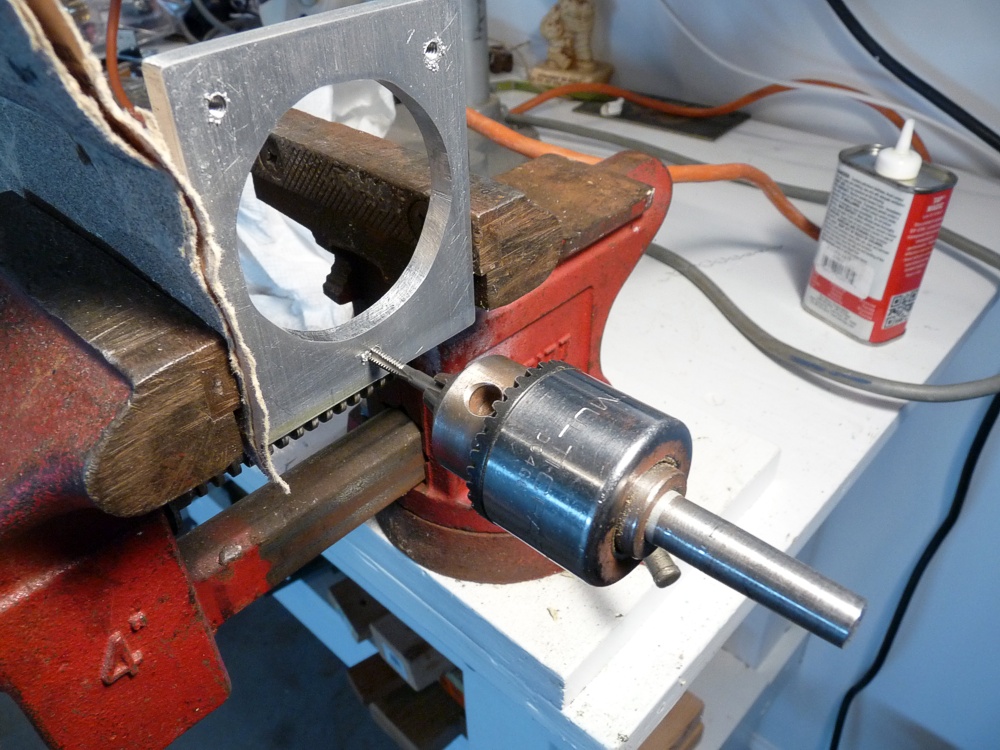
I drilled out the threaded holes in the original design lens board in favor of threading new holes in the much thicker spacer.

The adjustment range of the new design will permit perspective control on architectural pictures.

I found cheap springs at the local home improvement store and cut them to length with a Dremel tool.

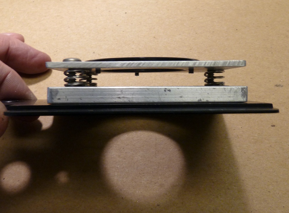
The springs are fairly stiff and the adjustment screws go most of the way through the 1/4″ space making the assembly quite rigid.

The hole in the stock Omega lens board is considerably larger than the lens mounting hole.
The rear of the lens extends up into the gap between the lens mounting plate and the Omega lens board.
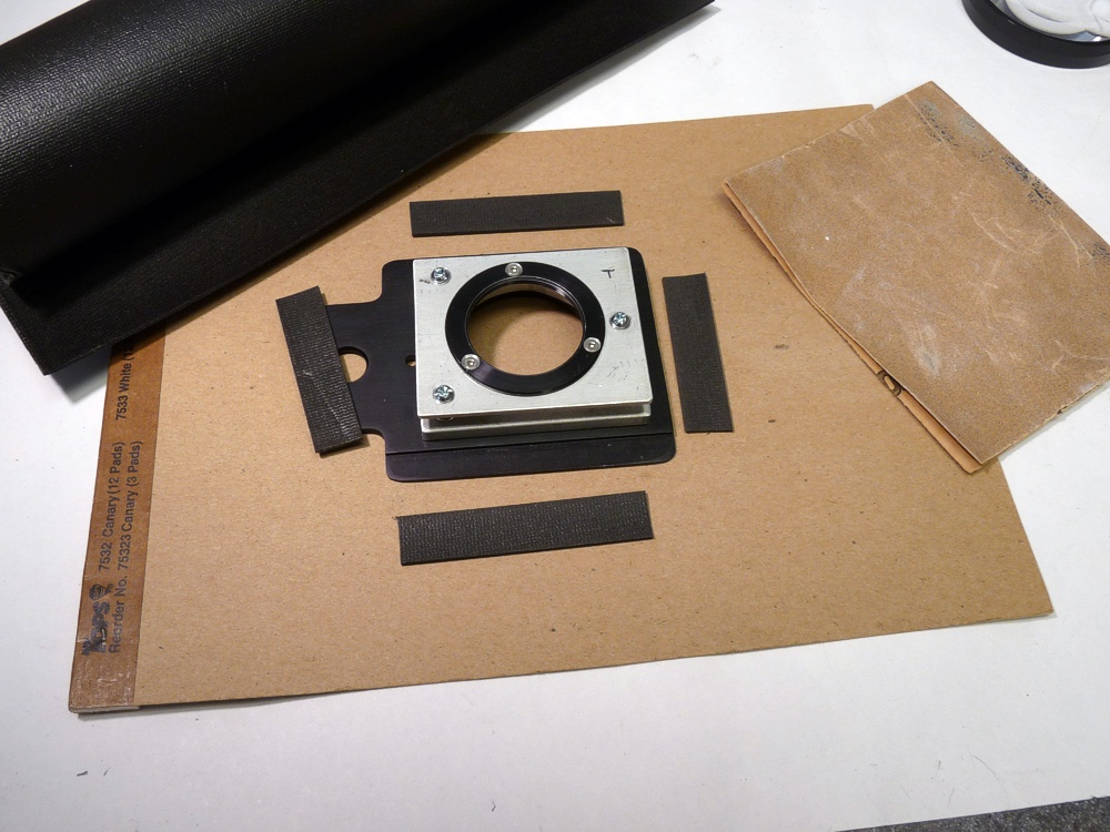
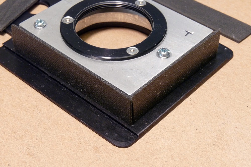
I used soft black foam shelf liner material to seal against leaks. I cut the strips, roughed up the glue surfaces with sand paper, and then epoxied them to the edges of the 1/4″ spacer.
Fitting the light seal strips before actually gluing them.

I sanded, primed, and painted the pieces to further reduce light leakage and reflections. I did not paint the surfaces that were to be glued.
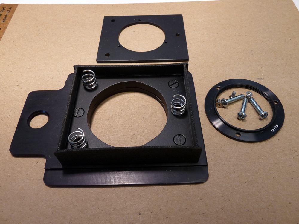
Spring placement and final assembly of the pieces.

As you can see, I ultimately settled on using Phillips head adjustment screws. I tested the 40 mm lens first to make sure the lens wasn’t too far away from the film plane to focus.

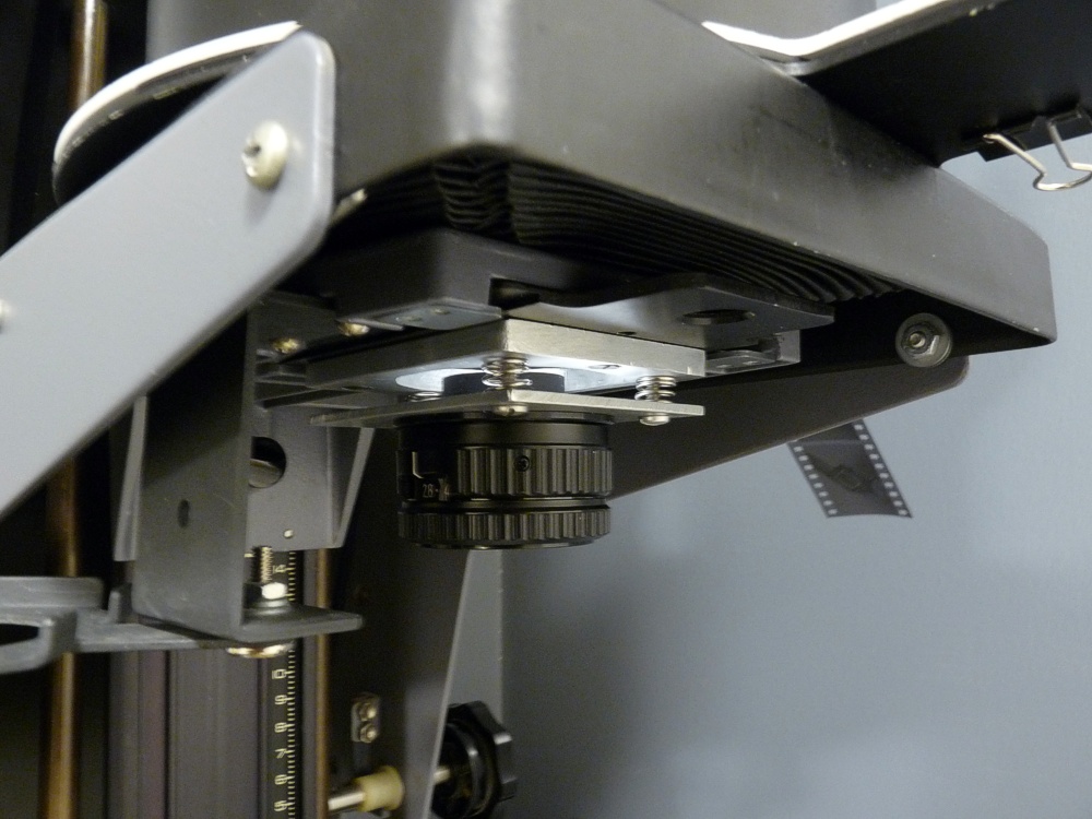
This shows how far back the lens extends toward the rear, but I will easily be able to slide the lens board out of the enlarger without having to unscrew the lens.

The 150 mm lens is the heaviest of my lenses, but will be held securely enough to keep it from moving when I change aperture settings.

The final product installed on the enlarger with my under-lens filter holder positioned under it.