While testing my recently acquired Hasselblad 501CM, I shot some pictures of my darkroom using the 40mm lens. The shots were hand held on TMax 100, so the depth of field was not great due to wide aperture, but it was as good a subject as any for test shots. This article simply puts those shots to use by explaining my darkroom setup. I like looking at pictures of other people’s darkrooms and I suspect I’m probably not alone. Darkrooms used to be so common that they were simply taken for granted. Now, being so rare, they seem to be more interesting. People who own classic cars like looking at pictures of other people’s classic cars, right? For me, my darkroom is like a time machine taking me back to the 1960s and 70s.
Below are the three pictures to which I have added numbers. Below the pictures I describe what the arrows are pointing to. Everyone with a darkroom arranges it to suit their preferences, so I am not presenting this as any kind of recommendation. The image files are about 3.5MB. If you click on them, they should open in your browser to full size, so you can zoom in. Note that many of the same items are identified in both pictures 2 and 3. The room measures 10′ x 12′ with the countertops running along the longer dimension. I should also note that the countertops are 30″ deep instead of the typical 25″ depth found in most kitchens. Since they are low cost and fabricated to order, you can specify the depth. The 30″ depth is needed for larger developing trays. The downside is that selenium toner stains laminate tops, but I’ve recently discovered a remedy for that!

Picture 1 Legend
- Paper developing working solutions. Stored in 1 gallon large mouth bottles so I can pour chemicals back into the bottles from the trays without the need for a funnel. No funnel, means you can pour very fast, especially useful for single tray developing which I do for 16″x20″ and 20″x24″ size prints. Items 2 – 6 below all refer to these print developing chemicals.
- D-72 developer. I track developer usage with hash marks on the label. I mix my own D-72 by the gallon in a 1+1 dilution ever since Kodak transferred its photo chemical product line to a UK company and the Dektol that I had used for decades mixed up looking like frothy coffee. I now mostly steer clear of Kodak branded chemicals and use any product labeled “New Formula” for target practice at the local shooting range.
- Indicator Stop Bath. I use it until it starts to turn color.
- Rapid Fixer. I use two rapid mixing baths (no hardener). I track the usage with hash marks on the label. I think this method is described on the data sheets for both Kodak and Ilford rapid fixers.
- Hypo Clearing Agent. I use it only when printing on FB paper and mix it up fresh before a session. I use the first HCA after fixing and the second HCA after toning. Since I’ve only been printing 8×10 FB prints lately, I only mix up a liter for each.
- Selenium Toner. I use it at a nominal dilution of 1:20. Aside from when I first mix it up, I never know exactly what the dilution is because I replenish it as I use it based on its effect and smell. I find that adding 2 ml per 8×10 is a good baseline. I used to only tone FB prints as part of my standard archival processing routine but now I tone all RC and FB prints because the deeper blacks make the prints look better.
- Two 1 gallon jugs of tap water. I keep tap water handy at room temperature for rinsing film between developer and fixer. It’s just easier (I am one lazy mofo) than checking the temp of the water coming from the tap which can be too cold in winter and too warm in summer. The temperature of my darkroom is 71F year round, so all the chemicals are also 71F.
- Paper developer timer. I like this timer, but I also modified it with automotive glass tinting film to reduce the brightness and orange filter material just to make it more darkroom friendly than it already was. I only use it with the safelights on, so it doesn’t have to be very bright.
- 12″x16″ Paterson trays. I would prefer 11×14 trays for 8×10 prints, but Paterson doesn’t make that size and I like these trays because of the well designed pour spout in the corner which allows me to pour the chemicals back into their respective large-mouth bottles very quickly without making a mess. For larger prints, I also have the 16×20 and 20×24 version of these trays, also because of the pour spout. On some trays (Yankee comes to mind), the pour spout is terrible. I’m guessing the designer has never poured any liquid out of the tray he designed, just like the guy who made the design improvements to the Yankee bullet-shaped safelights never had to actually use them.
- Metal Tongs. These are good tongs. They stay springy and don’t damage prints. Like everything that I worry will someday go out of production, I have extras.
- Film chemicals. These are almost all film developers that have been decanted into smaller containers. I have some Ilfotec HC from 2013 which still works like new. I don’t really use it for anything, but I test it every now and then just because I’m curious which of us will outlive the other.
- Raw chemicals. I don’t use them very often, but when I find something I might want to try, I’ll often buy the chemicals so I’ll have them in case I ever do. I have experimented with several film and paper developing formulas as well as bleaches and toners.
- Liquid measuring devices. Graduated cylinders, measuring cups, funnels, spoons, eye droppers, syringes, etc. Measuring containers suffer from the same design flaws as trays in that the pour spout often allows the liquid to run down the outside of the cup. I’m fully aware that I may be the only darkroom owner on the planet who obsesses over little shit lie this.
- Print bleaching board. This panel swings down to an incline over the sink for bleaching prints. It has a laminate surface and aluminum edging. It also has a little sign that reads, “CAUTION! This board is heavy! It will hurt a lot if it falls on your head!”
- Premier 8″x10″ amber “OC” safelight. This is from back in the days when you could still buy high quality OC safelights brandy spankin’ new. I use OC safelight when I am printing pictures.
- Premier 5″x7″ red safelight. Red safelights are still available new. I use red safelights for developing otho litho sheet film for contrast masks. Why would they stop making OC safelights and keep making red safelights? I suspect it was yet another decision made by someone who’s never seen the inside of a darkroom.
- Articulated desk lamp. This was originally intended for use with the bleaching board, but it’s become the light I use now whenever I’m too lazy to walk all the way over to the wall switch to turn on the overhead lights.
- Room thermometer. This tells me whether the darkroom is 71F or 72F which seems to be the total temperature variance of the room. Kudos to whoever designed central heating and cooling. We have three heat pumps in my house. No one is allowed to change the setting on the one that controls the darkroom. NO ONE!
- Cordless telephone. I added little black flaps to this phone that cover the buttons and display screen so it doesn’t emit any light if someone calls unless I flip up the flap to see what robocaller is bothering me this time.
- Fixer timer. This timer is also modified using automotive window tinting film to make it dimmer. The time is set to either 30 or 60 seconds depending on whether I’m printing on RC or FB paper. It has a power switch but the display turns off by itself after a few minutes, so I leave it powered on all the time. That way it remembers the time so I don’t have to set it. I have lazy down to a science. Fixer gets its own timer because, with the two bath method, I have to use it twice for each print. Haha! Just kidding. I’d still have a dedicated fixer timer even if I used only one fixing bath.

Picture 2 Legend
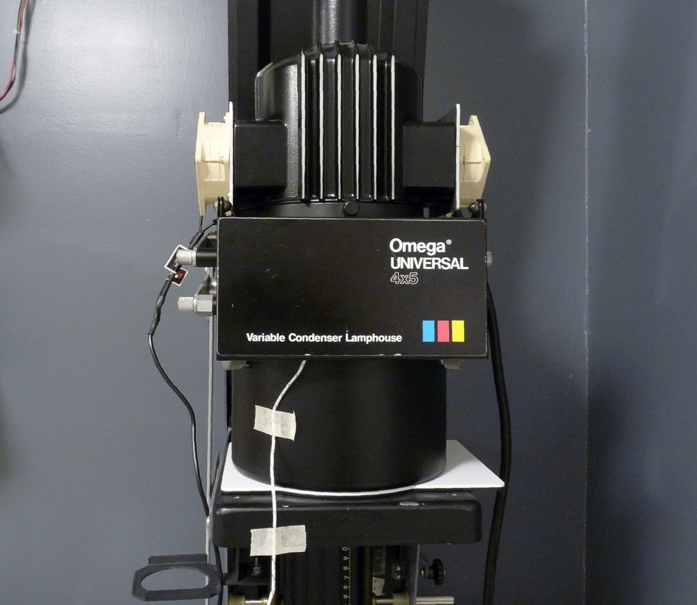
- Omega 4″x 5″ Chromega enlarger. This has the tall column which, like the table it is mounted to, is bolted to the wall for stability. This part of the house has a slab foundation, so it’s pretty rigid. I’ve had this enlarger since the 1990s and have done B&W and Cibachrome printing with it.
- Dodging wands. I often make custom dodging and burning tools on the fly for a specific image. I label them with the negative number and print size and store them in a draw where I never use them again because who wants to look through a draw with hundreds of poster board shapes when it’s easier to just make a new one?
- RH Designs Stop Clock Timer. For Chromega enlarger. Maybe the most thoughtfully designed darkroom timer ever made. When I first bought it, I thought it was expensive. Now I think, considering how well designed it is, I consider it a bargain.
- RH Designs Zonemaster II. For Chromega enlarger. I could say the same for the Zoenmaster as I did for the Stop Clock. Both devices reduce trial and error attempts to get a perfect print. They will make your prints better because they will get you to a nicely exposed print before you get frustrated and settle for something less than perfect. Side benefits are that they will also make you easier to live with and reduce your use of profanity.
- Dahle 552 20″ paper trimmer. This comes in handy for cutting large photo paper down into smaller sizes from which test strips can be cut. I bought a smaller 12″ guillotine-style cutter on ebay strictly for cutting 2″ x 5″ test strips which are usually fine for printing 8x10s. For larger prints, I may do test strips in multiple places in the image space to sample all the important tones.
- Enlarger selection switch. Since I have two enlargers (diffusion and condenser), I also have two timers, each of which automatically shuts off the safelights during focusing or exposure. This switch simply connects the safelights to whichever timer I’m using.
- Stop Clock Timer. For Condenser enlarger. See item 3 above for description.
- Refridgerator. I use this mostly for film, but I also refrigerate Xtol type developer in 16 oz glass bottles. I’ve found that the developer has a longer shelf life if kept cold. Since this fridge has no freezer, I never have to defrost it. Defrosting is an objectionable task for people with stage 4 laziness such as myself.
- Enlarger bases. These are removable table tops associated with the Condenser enlarger. Since the ceiling limits the height to which I can raise the enlarger head, I can effectively lower the base by removing upper level tabletop(s) and placing the easel on a lower level. Generally, the only time I do this for extreme cropping. I can project all the way down to the floor.
- 16″x20″ Saunders 4-blade easel. This is their conventional (not the V-Track) easel. For the occasional 20″x24″ print, I have a home built easel without adjustable blades.
- Zonemaster Meter. For Condenser enlarger. See item 4 above for description.
- Door mounted exhaust fans. You can only see one in this picture, but I have two 8″ fans mounted on Doran light tight vents on the door. They just blow air out of the darkroom into the adjoining “frame shop”. Yeah, I probably wouldn’t be the first person anyone would hire to design a safe biochemical research facility, but aren’t toxic fumes part of the charm of chemical based hobbies?
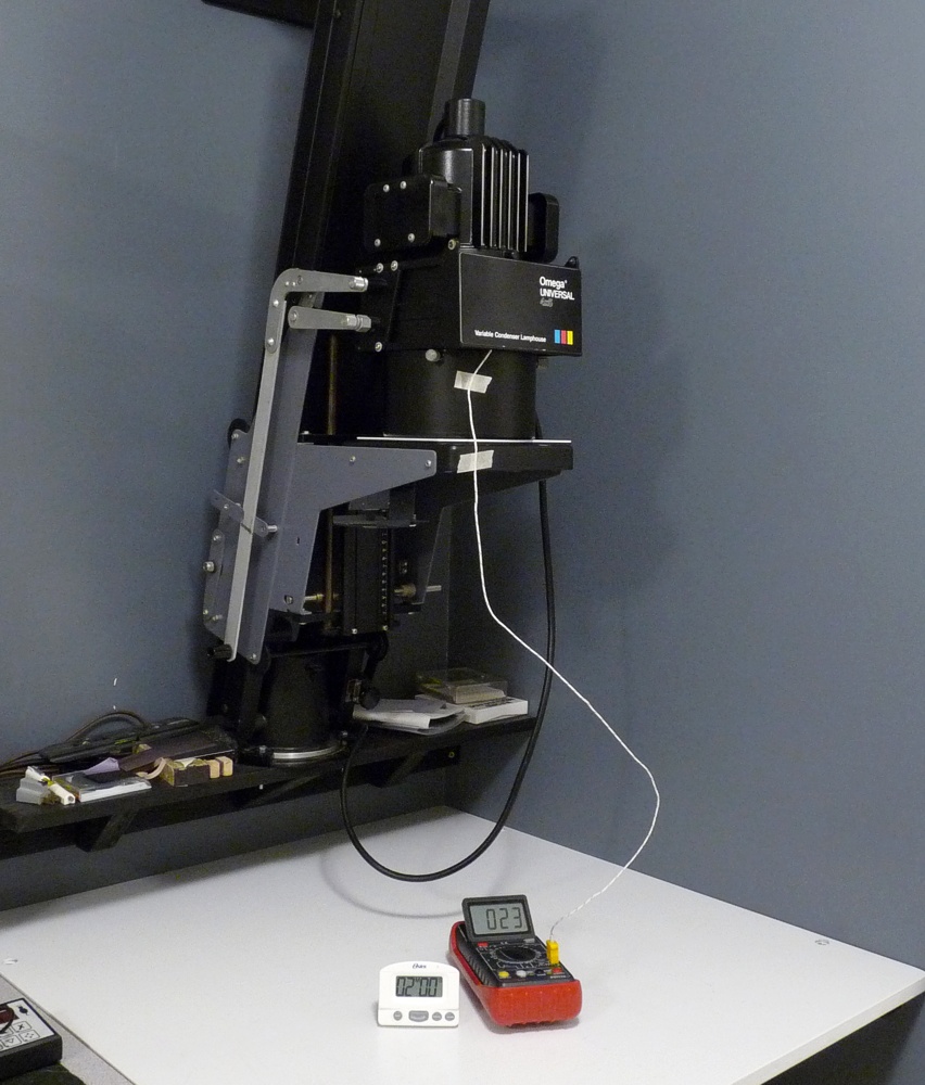
- Omega 4″x 5″ DV condenser enlarger. This enlarger has the short column. The base is mounted in a slightly elevated position on a wall mounted shelf/bracket with a wall mounted top brace. When raised to the top, the lamp house just touches the ceiling and I have to stand on a step ladder to swap out the 6×6 contrast filters. One of the main reasons I have been using this enlarger for recent work is because I like having contrast filters above the negative.
- Yankee Bullet-shaped safelight. This safelight, as purchased new, is unusable for anyone able to recognize that a translucent white plastic enclosure for a safelight is a bad idea. But, it can be modified to work.
- Pre-flashing lamp. This is just a coffee can with an incandescent nightlight bulb mounted inside and a small filter frame on the open end facing down. The filter frame holds a #00 Ilford contrast filter and a UV filter from a Cibachrome color filter set. Pre-flashing a sheet of phot paper simply raises the sensitivity of the paper so that less additional light light is needed to create a very light gray tone. This tends to alter the foot of the paper sensitivity curve such that highlights can be more easily printed without washing out to pure white. I do this quite often when I want to maintain contrast in the mid tones while still having some detail in bright highlights. The secret is to always keep the pre-flash exposure time short enough so that it doesn’t, by itself, fog the paper. I control the exposure with the timer described in item 22 below.
- Premier 5″x 7″ amber OC safelight. I added this safelight when I started using the condenser enlarge became my primary printing station. That corner was quite dark and it’s difficult to shade a test strip for multiple exposures when you can’t see it. Later I added another safelight (item 14 above) to make it even easier to see. Despite having two safelights pointing down at the easel, it is still not very bright. I tend to err on the dim side for darkroom lighting.
- Speakers (only one is visible). I have speakers for the sound system (item 20 below) mounted above the door at each corner of the door frame. I have an identical pair of speakers mounted above the door in the same place except facing out into the frame shop. They are wired so the left and right stereo channels don’t change sides when I walk out into the frame shop from the darkroom.
- Premier 5″x7″ red safelight. Red safelights are still available new. I use red safelights when exposing and developing otho litho sheet film to make contrast masks. They are not controlled by teh enlarger timer and, therefore, not turned off contrast mask exposures. The red safelights are off when I’m doing normal printing.
- Premier 8″x10″ amber “OC” safelight. Last time I tried to by one of these, I couldn’t find them available new. I use OC safelight when I am printing pictures.
- Sounds system. This is an old 5.1 home theater sound system that I use to play music or podcasts from my little mp3 player or from my tablet. I use it in stereo mod, with the left and right channel each having two speakers wired in parallel. One pair of speakers is in the darkroom and the other pair are in the adjacent frame shop. You can see that the subwoofer is also in the darkroom. For podcasts I tend to use a bluetooth headset since my hearing isn’t that great anymore.
- Safelight power strip. All the orange safelights in the darkroom are controlled by whichever Stop Clock timer is in use. To be accurate, the enlarging meter (item 4 above) require that all the safelights be turned off when making exposure measurements. Power to these outlets is supplied from the enlarger selection switch (item 6 above).
- Pre-fash exposure timer. This is a GraLab model 300 timer. I keep the face of it covered with black poster board when I’m not using it because the green glow-in-the-dark dial seems very bright when it’s “charged up” by the white room lights. It controls the pre-flash lamp (item 15 above). I do pre-flashing often, so a dedicated lamp and timer are warranted.

Picture 3 Legend
- Large liquid measuring devices. These include taller items like graduated cylinders and measuring cups up to 5 liters. I also have a water spray bottle up there for wetting the paper take that I use to tape wet FB prints to glass to dry.
- Glass chemical storage bottles. These are new unused glass bottles that are used to decant developer concentrates and working solutions so that most of my chemicals are in full tightly capped bottles to ensure a long shelf life. I also use plastic (PET and LDPE) bottles, but in my experience, glass is a much better oxygen barrier.
- Black foamcore. I put this up to reduce white light from the easel being reflected back down from the ceiling. I did it on a whim without any reason to believe it was actually even a real problem. Since I started using Zonemaster meter, I am confident that that light scatter is not a significant issue in my darkroom.
- Yankee Bullet-shaped safelight. This safelight, as purchased new, is unusable for anyone able to recognize that a translucent white plastic enclosure for a safelight is a bad idea. But, it can be modified to work.
- Room thermometer. This tells me whether the darkroom is 71F or 72F which seems to be the total temperature variance of the room. Kudos to whoever designed central heating and cooling. We have three heat pumps in my house. No one is allowed to change the setting on the one that controls the darkroom. NO ONE!
- Cordless telephone. I added little black flaps to this phone that cover the buttons and display screen so it doesn’t emit any light if someone calls unless I flip up the flap to see what robocaller is bothering me this time.
- Grabber/Reacher and fly swatter. The grabber is to reach items on high shelves. The shelves go up to the ceiling in the darkroom and I’m only 5’8″ tall. The fly swatter is because I live in Alabama and apparently a lot of flies also live here. Flies are not welcome in my darkroom (or anywhere else in my house).
- Omega 4″x 5″ Chromega enlarger. This has the tall column which, like the table it is mounted to, is bolted to the wall for stability. This part of the house has a slab foundation, so it’s pretty rigid. I’ve had this enlarger since the 1990s and have done B&W and Cibachrome printing with it.
- Metal rulers. These are various lengths (12″, 18″, 24″, 48″) and are used as general purpose straight edges. One of them is a thick aluminum straight edge for cutting glass.
- My old paper safe. This is just a wood box with shelves inside. The inside is black. I’ve used this as a paper safe for decades and can honestly say that it is a really crappy paper safe. I have since built a new paper safe.
- Borderless easels and plexiglas sheets. I can’t remember the last time I used a borderless easel. I used the plexiglas sheets to cover stop bath and fixer trays when I take a break from printing that I expect to last for more than a half hour or so. I cover the developer tray by floating an identical tray on top of the developer surface like a floating lid, which prevents oxidation. I also cover my fixer tray when I tone prints which I do immediate after I print each picture. It eliminates the possibility of toner splashing into the fixer which is something I try to avoid for reasons I can no longer remember. I never leave chemicals in the trays over night.
- My new paper safe. This consists of two drawers, one above the other. Best paper safe I’ve ever had.
- RH Designs Stop Clock Timer. For Chromega enlarger. Maybe the most thoughtfully designed darkroom timer ever made. When I first bought it, I thought it was expensive. Now I think, considering how well designed it is, I consider it a bargain.
- Dahle 552 20″ paper trimmer. This comes in handy for cutting large photo paper down into smaller sizes from which test strips can be cut. I bought a smaller 12″ guillotine-style cutter on ebay strictly for cutting 2″ x 5″ test strips which are usually fine for printing 8x10s. For larger prints, I may do test strips in multiple places in the image space to sample all the important tones.
- Enlarger base. The upper table top for the Chromega (diffusion) enlarger is removable. By removing the table top and placing the easel on a lower level I can do more extreme cropping when it’s called for.
- Step stool and kneepad. The 6″ step stool is handy for reaching high shelves while the kneepad is for when I’m using the lower tables (or the floor) for printing. To look through a grain focuser when the printing easel is only a few inches off the floor I have to be kneeling on a very hard floor.
- Dish drying rack (barely visible). It where I place bottles, tanks, reels, and measuring cups to dry after they’re washed.
- Refridgerator. I use this mostly for film, but I also refrigerate Xtol type developer in 16 oz glass bottles. I’ve found that the developer has a longer shelf life if kept cold. Since this fridge has no freezer, I never have to defrost it. Defrosting is an objectionable task for people with stage 4 laziness such as myself.
- RH Designs Zonemaster II. For Chromega enlarger. I could say the same for the Zoenmaster as I did for the Stop Clock. Both devices reduce trial and error attempts to get a perfect print. They will make your prints better because they will get you to a nicely exposed print before you get frustrated and settle for something less than perfect. Side benefits are that they will also make you easier to live with and reduce your use of profanity.
- Enlarger selection switch. Since I have two enlargers (diffusion and condenser), I also have two timers, each of which automatically shuts off the safelights during focusing or exposure. This switch simply connects the safelights to whichever timer I’m using.
- Pre-fash exposure timer. This is a GraLab model 300 timer. I keep the face of it covered with black poster board when I’m not using it because the green glow-in-the-dark dial seems very bright when it’s “charged up” by the white room lights. It controls the pre-flash lamp (item 15 above). I do pre-flashing often, so a dedicated lamp and timer are warranted.
- Various small scales. These are used for weighing small amounts of dry chemicals for mixing various photo chemicals (developers, toners, bleaches, etc.). Some have a resolution of 0.01 g and others read in increments of 0.1 g. On the very top shelf there is a larger scale for weighing up to 50 lbs.
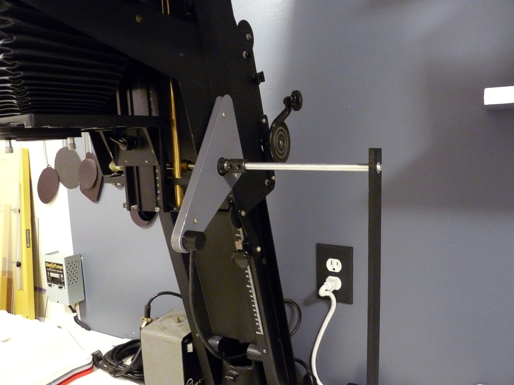
- Enlarger alignment thingamabob. This is a little 3D printed device to which a standard rail-mounted laser sight is attached. By placing on the easel under your enlarger, you can adjust the lens and negative carriers to perfectly parallel to the plane of the easel. The laser beam is precisely perpendicular to the easel and you can tell when the lens board and negative carrier are parallel when the laser beam is reflected back down into the laser projector.