Bcakground
In my last article, I conducted some temperature tests using the 250W PH213 lamp in the Omega DV Condenser lamphouse. Omega offered a blower for the DV lamphouse that permitted use of 250W bulb. The Omega part number is 412-020. I’ve never seen one, but it is listed on the KBH Photografix website.
As expected, with no blower, the 250W bulb generated considerably more heat than the 150W bulb, exceeding 200 F between the bulb and heat absorbing glass. This article describes my adventures in adding a pair of small fans to the lamphouse to try and reduce the heat buildup from the higher wattage bulb.
Construction
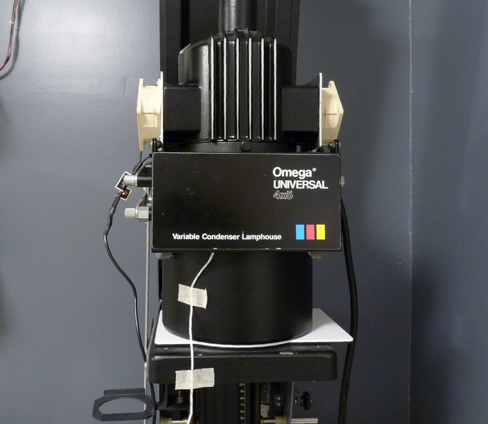
The first step was to remove the plastic covers on each side of the lamphouse. These covers permit air to flow into the sides of the lamphouse and exit through an opening in the top, cooling by convection. The bulb is completely enclosed within an inner chamber preventing any light leakage through these ventilation openings. For this project I decided to attach a 12 VDC 60mm low speed computer fan (Noctua NF-A6x25 FLX) available from Amazon to each side of the lamphouse, both blowing air inwards. The low speed will minimize noise and vibration and the speed can be controlled by simply reducing supply voltage (or adding resistance in series with the power). The down side is that a small fan running at low speed doesn’t move a lot of air.

Noctua NF-A6x25 FLX 60mm Fan
To attach the fans, I designed a mounting plate that can be attached to the lamphouse using the existing threaded holes previously used to attach the plastic covers. Since the #6-32 threading in those holes does not extend very deep into the holes, I used the original self-threading screws to deepen the threads. I simply worked the screws in and out, each time going slightly deeper. My #6-32 tap has a pretty long taper and I was afraid it would bottom out sooner than the screws.

Fan Mounting Plate (dimensions approximate)
I cut the plates out of some 0.092″ thick scrap aluminum I had lying around and started marking and drilling. As you can tell, I am much more inclined toward functionality than prettiness. Also, I’m kind of lazy and have a short attention span, so I needed to keep the project within the limited range of my mechanical skills.

Cut scrap aluminum to size and started drilling.
To cut the fan hole, I screwed the plate to a piece of wood so I could rotate it around as I cut it with my jig saw (aka sabre saw).
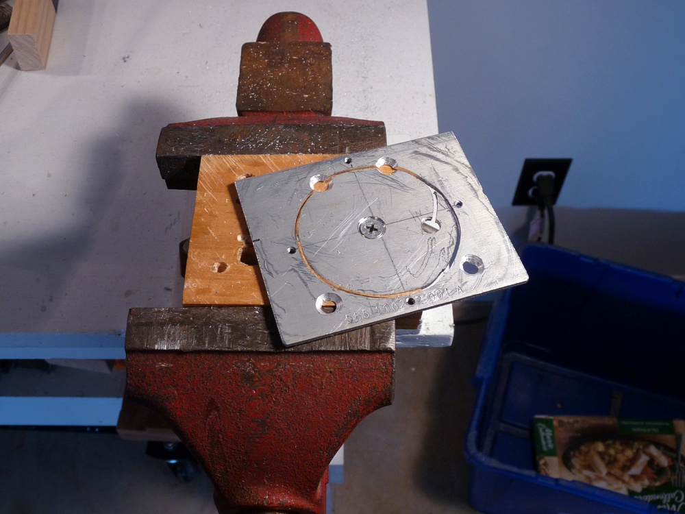
Jig to cut the main hole in the plate. (the 2 holes at the bottom do not need to be countersunk).
As you can see, the hole placement does not lend itself to easy assembly. I wanted to mount the fan to the plate and then mount the plate to the lamphouse. Unfortunately, two of the screws that mount the plate to the lamphouse are under the fan. The problem solved itself, however, because the upper two screw holes were bisected by the fan cutout. I installed those two screws into the lamphouse and simply slid the fan plate (with the fan installed) down under them. Then I simply installed the two lower screws. Note that I countersunk all four holes, but the countersinking is only needed for the top two screws which are trapped under the fan.

Hook the plate under the upper two screws (already installed) and then install the lower two.
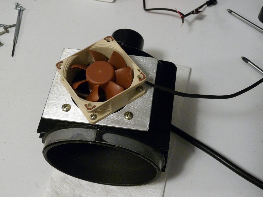
Fan plate with fan attached (this is actually the second fan plate).
I got a variable 3- 12 VDC fan power supply from Amazon to power the fans, but left the task of dressing up the wires until after doing the testing. Ultimately, the fans were wired together and the wire routed along side the main lamphouse power cord so as to be out of the way.
Results
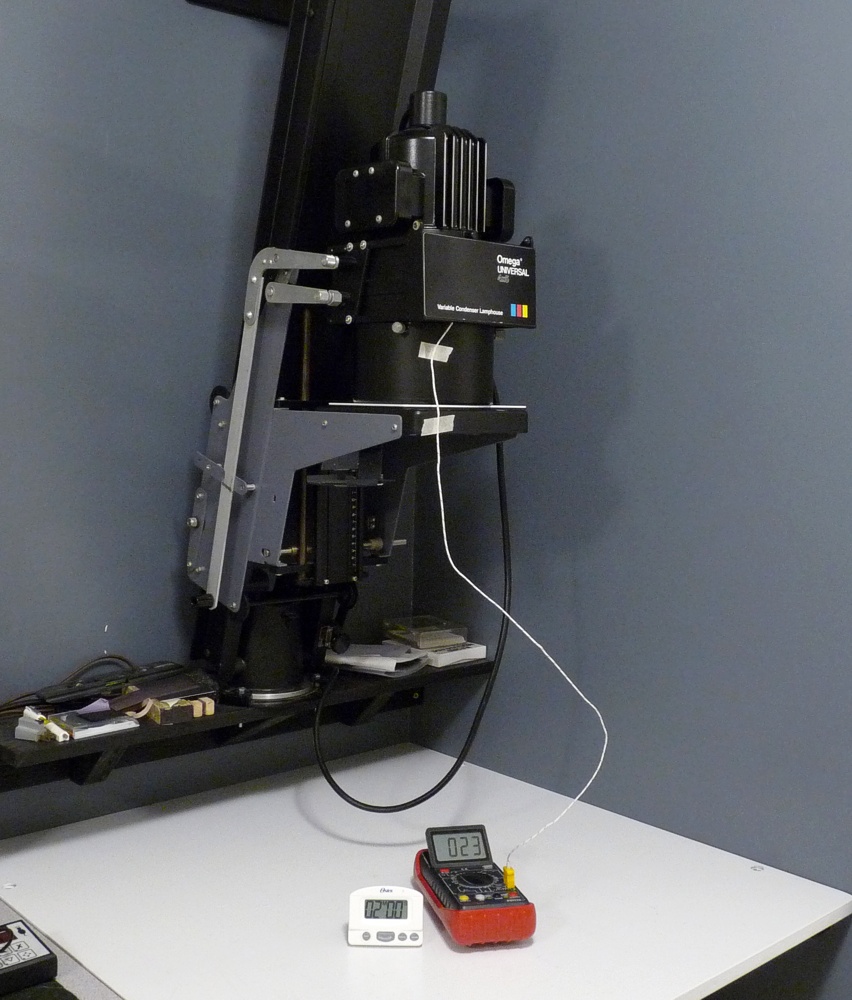
Test setup. Thermocouple placement was identical before and after fans.
The “Before Fan tests” were conducted with the original plastic covers still in place before work started on the fans. The thermocouple was then left undisturbed as I added the fans so as to ensure no other variables were introduced in the test results. I have heat absorbing glass installed in the top slot of the variable condenser housing. The thermocouple was centered in the middle of the heat glass and suspended 0.500″ above the surface and 0.700″ below the bulb. I measured this before the fans were added and after the fans were added to make sure nothing changed. Experiments are worthless if the conditions of the test are inadvertently altered during the test. The variable speed controller was set to maximum output (12 VDC) for all of the tests with the fans.
The results are tabulated below. The results with no fans are the same measurement collected for my previous article. I started each test with the temperature stabilized at room temperature. I had the lamp turned on for 120 seconds and then turned off for 120 seconds. Temperature readings were made at 30 second intervals on the ramp up and on the cool down.

Temperature comparison with fans and without fans.
While the fans certainly do reduce the temperatures, I was hoping for better than this. My goal was to keep the temperature range for the fan cooled 250W bulb more in line with the temperatures generated by the convection cooled 150W bulb. That was overly optimistic given the fact that the airflow never actually touches the bulb which is enclosed in its own chamber. On the bright side, the cool down time is definitely accelerated by the fans. After the 250W lamp has been off for the 2 minute cool-down, the temperature (111.2 F) is very close to that of the 150W bulb with no fans (109.4 F).
For those who are wondering, I did run one test to see if the cooling performance was different if one fan was flipped to blow out instead of inwards. The performance was measurably worse, so I reverted to having both fans blowing inwards.
Noise
I measured the acoustic noise of the modified condenser lamphouse against the noise generated by the fan in my Chromega with the noise meter 10″ in front of the respective enlarger heads. As you have probably guessed, the reason for the noise test is to get an idea of whether the fans could induce vibration that diminishes print sharpness. The heads on these enlargers are massive compared to the mass of the spinning fan blades, so the risk is presumably quite small.
- Modified Omega DV Condenser Lamphouse: 43.5 – 44.5 dBA
- Standard Chromega Lamphouse: 46.5 – 47.5 dBA
- Ambient Noise Floor: 38 – 40 dBA
For the hell of it, I listened to each of them using a stethoscope and the Chromega was noticeably louder.
But What About Temperatures at Negative Plane
Measuring the temperature at the negative plane with the 250W bulb and starting at 23 C (73.4 F) ambient, I got a thermocouple reading of 27 C (80.6 F) after the lamp had been on for 120 seconds. With the 150W bulb, the reading was 25 C (77 F) after 120 seconds. While not hot enough to damage the negative, this may be enough to cause the negative to “pop” out of focus. This is of little concern to me since I use glass carriers.
I use heat absorbing glass (Omega p/n 473-103) in my condenser enlarger and I don’t have any test results without having the glass installed in the uppermost shelf in the variable condenser housing. Since I never use a 135 mm lens, I never have to install the movable condenser lens in that slot. For 4x5s, I use 150 mm which eliminates the movable lens completely.
Finally, and this applies to this article as well as the previous one, thermocouples do not react instantly to temperature changes and we are dealing with a short time line for these tests, so the actual temperatures are likely to have been somewhat higher than the numbers recorded during these tests. Nonetheless, I think the tests do provide useful information for comparison purposes between the three different wattage bulbs tested. It also satisfied my curiosity about how practical it is to use a 250W bulb in the Omega DV condenser lamphouse.
Having now added the fans, I believe I will be quite comfortable using the 250W lamp when necessary for large magnifications or to shorten exposure times for dense negatives.